Sheet metal fabrication is a core manufacturing process, widely used in a variety of fields, including construction, automotive, and aerospace. Its versatility and ability to be formed into a wide variety of shapes and sizes make it an ideal choice for achieving complex designs and precise structures.
To ensure the success of sheet metal fabrication projects, a thorough understanding of its design principles and best practices is essential. This article provides a comprehensive guide to sheet metal fabrication design, covering material selection, geometric constraints, and cost-effective design strategies.
Whether you are an experienced engineer or a novice designer, this guide will help you create high-quality sheet metal parts that meet project requirements and specifications.
What is sheet metal fabrication?
Sheet metal fabrication is a manufacturing process that creates parts of various shapes and structures by cutting, bending, stretching, and forming sheet metal. It is widely used in construction, automotive, aerospace, electronics, and appliances, producing products ranging from simple enclosures to complex, precision components. Due to its low cost, high production efficiency, and flexibility, sheet metal fabrication has become an indispensable technology in modern manufacturing. How Sheet Metal Fabrication Works
Sheet metal fabrication is a combination of subtractive and forming processes. Its core principle is to transform flat metal sheets (called sheet metal) through specific machining steps to create the desired three-dimensional part.
Digital Design (CAD) → Programming (CAM) → Cutting → Forming → Secondary Processing (such as deburring) → Connection and Assembly → Surface Treatment (such as painting and plating) → Finished Product Inspection
The entire process is typically controlled by computer numerical control (CNC) equipment, ensuring high precision, efficiency, and product consistency. Simply put, it's like using scissors and origami to process solid sheet metal, ultimately creating a variety of useful metal parts.
Detailed Explanation of Sheet Metal Fabrication Technology and Processes
Laser cutting: Uses a high-powered laser beam to precisely melt and ablate material, offering high precision and flexibility, making it a mainstream modern processing method.
Plasma cutting: Uses a high-temperature, high-speed plasma arc to melt and blow away metal, making it more suitable for cutting thicker sheets. Stamping: Using a punch press and die, sheet metal is punched with strong pressure. It is highly efficient and suitable for high-volume, fixed-shape parts.
Bending: The most common forming process. A press brake and die are used to apply pressure to the sheet metal, bending it to a specific angle at a predetermined location.
Stamping: Using a die to perform one or more press strokes on a punch press, complex shapes such as concave and convex, relief, and louvers can be created.
Rolling: Using a set of rollers to continuously bend the sheet metal, used to create tubular or conical parts.
Deep drawing: Pulling the sheet metal into a die cavity creates deep-cavity parts such as cups or boxes, such as automotive fuel tanks and stainless steel sinks.
Advantages and Disadvantages of Sheet Metal Fabrication in Manufacturing
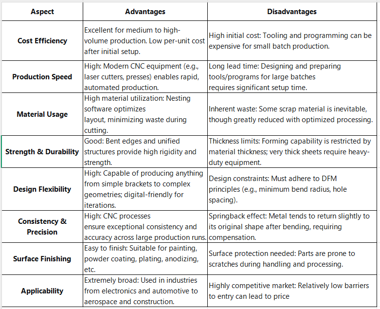
Sheet metal fabrication is ideal for mass production of structural parts, housings, brackets, chassis, and other products with uniform wall thickness. It offers an excellent balance between cost, efficiency, and strength.
When choosing a sheet metal fabrication process, keep in mind that the initial cost may be higher for small-batch prototyping. Furthermore, the design must fully consider the constraints of the manufacturing process, otherwise problems may arise. Below is a chart comparing the advantages and disadvantages of sheet metal fabrication.

Sheet Metal Fabrication Design Requirements
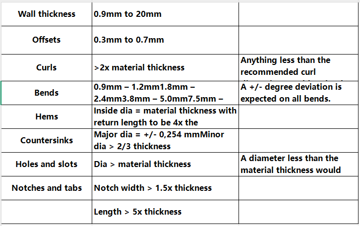
When designing for sheet metal fabrication, a series of key requirements must be adhered to to ensure the quality, precision, and cost-effectiveness of the final product. First, the designer needs to fully understand the material's characteristics, such as thickness, strength, and ductility, and select the most appropriate material for the application. Second, the design drawings must be clear and accurate, including all necessary dimensions, tolerances, hole locations, bend angles, and radii to avoid misunderstandings during production. Furthermore, the design should consider the feasibility of the fabrication process. For example, overly complex structures should be avoided to reduce unnecessary steps and costs, and sufficient operating space and reasonable tolerances should be reserved for processes such as welding and bending. Finally, surface treatment requirements (such as painting and plating) should be determined during the design phase. This not only affects the product's appearance but also its durability and corrosion resistance. An excellent design strikes the optimal balance between meeting functional requirements and simplifying the manufacturing process. Tolerance Additional Notes Table

Common Sheet Metal Design Mistakes and How to Avoid Them
In sheet metal fabrication design, designers need to avoid some common mistakes to ensure product manufacturability, functionality, and cost-effectiveness. The following is a detailed analysis of these mistakes and their corresponding avoidance methods. 1. CAD Model and Development Drawing Issues
Error Description
CAD Files Not Considering Bends: The CAD model provided to the manufacturer shows the part as flat, without bends, but bending is required in production. This prevents the part from being manufactured as a single piece, requiring additional joining steps and costs.
Development Drawing Error: The overall blanking dimensions (defined as the developed dimensions) are either too small or too large, inconsistent with the final rounded surface. This is typically due to an engineering development calculation error or incorrect blanking dimensions.
Prevention Methods: Complete CAD Model: Create a complete 3D CAD model during the design phase, including all bending features, and ensure the model can be correctly developed. Communicate with the manufacturer to confirm their CAD file requirements.
Accurate Development Calculation: Use professional CAD/CAM software for development calculations, taking into account parameters such as material thickness, bend radius, and K factor to ensure accurate developed dimensions.
2. Features Too Close to the Bend Line
Error Description
Hole, cutout, or edge close to the bend line: When holes, cutouts, or part edges are too close to the bend line, these features are susceptible to deformation, tearing, or dimensional inaccuracies during the bending process.
Slots Too Close to the Bend: Slots too close to the bend may cause them to deform or collapse during the bend, resulting in uneven edges.
How to Avoid This
Minimum Distance Requirements: Ensure that all features (such as holes and cutouts) maintain sufficient distance from the bend line. Generally, this distance should be at least twice the material thickness, or adjusted based on the specific bend radius and material properties.
Design Specifications: Follow Design for Manufacturability (DFM) specifications for sheet metal fabrication. For example, the recommended distance from a hole to the bend root is the bend radius plus the material thickness, or at least twice the material thickness.
3. Unreasonable bending design
Error description
Too small bending radius: Designing a bending radius that is too small may cause the material to crack at the bend, especially for thicker materials or certain specific materials (such as high-strength steel).
Uneven wall thickness: In areas with more bends, it is easy to cause uneven wall thickness, affecting the strength and precision of the parts.
Vertical angle design: Designing a perfect 90-degree vertical angle is difficult to achieve in sheet metal processing and may cause stress concentration.
Avoidance method
Reasonable bending radius: Select the appropriate minimum bending radius according to the material type and thickness. Generally, the minimum bending radius should be at least equal to the material thickness, or according to the material supplier's recommendations [7].
Uniform wall thickness principle: When designing the structure, especially in the bending area, the wall thickness should be kept uniform as much as possible to ensure processing quality and product performance.
Avoid sharp angles: When designing the bending angle, a certain fillet radius should be allowed instead of a perfect sharp angle to reduce stress concentration and improve manufacturability.
4. Hole Design Issues
Error Description
Aperture Diameter Too Small: Apertures designed too small, especially those smaller than the material thickness, can damage stamping tools, increasing production costs and time.
Hole Spacing Too Close: Holes too close together, or too close to the edge, can lead to insufficient material strength, causing deformation or tearing during processing or use.
Avoidance Methods
Minimum Hole Diameter: The hole diameter should be at least equal to the material thickness, and preferably larger, to reduce tool wear and damage.
Appropriate Hole Spacing: Ensure sufficient spacing between holes and between holes and edges. A typical recommendation is twice the hole diameter or twice the material thickness, depending on the material and processing process.
5. Improper Tolerance Setting
Error Description
Tolerances Too Tight: Setting excessively tight tolerances exceeds the capabilities of the sheet metal processing process, resulting in high scrap rates and increased costs.
Tolerances Too Loose: Setting tolerances too loosely can lead to poor part fit or functional failure. Avoidance Measures
Machinability Tolerance: Machinability tolerances are set based on factors such as the processing method, material, and dimensions. For example, in sheet metal processing, the distance tolerance between holes is typically around ±0.05mm, and the tolerance from the hole to the bend root is around ±0.15mm.
Communicate with the Manufacturer: Communicate with the manufacturer during the design phase to understand the accuracy and process capabilities of their equipment so that reasonable tolerances can be set.
6. Improper Material Selection
Error Description: Material Mismatch: The selected material is not suitable for the product's application environment (e.g., corrosion resistance, strength requirements) or processing technology (e.g., poor bending performance).
Avoidance Measures
Comprehensive Assessment: Thoroughly evaluate and select the most appropriate sheet metal material based on the product's functional requirements, operating environment, cost budget, and processing requirements.
7. Welding Design Issues
Error Description: Welding Defects: Failure to fully consider the welding process in the design can lead to weld defects such as cracks, pores, and lack of fusion, affecting the product's strength and appearance. Welding manufacturability: Consider welding manufacturability during the design phase. For example, reserve sufficient space for welding operations, avoid complex welding paths, and specify appropriate welding types and parameters.


